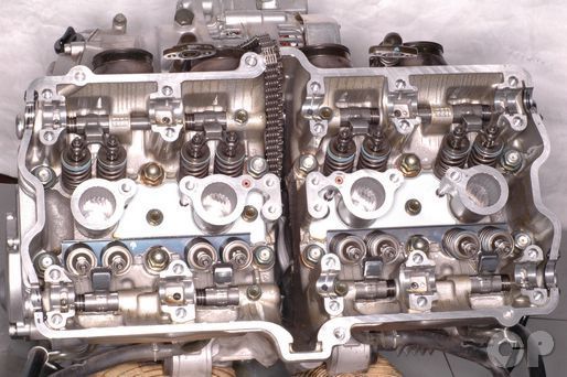
Cylinder Head
SAFETY FIRST: Protective gloves and eyewear are recommended at this point.
Removal
Remove the cylinder head cover. See the Cylinder Head Cover topic for more information.
Remove the camshaft. See the Camshaft topic for more information.


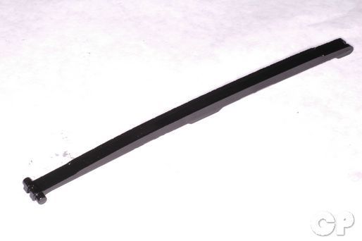
Inspect the condition of the cam chain guide. Replace the guide if it is overly worn or damaged.


Remove the cylinder head bolt on the front of the engine with a 10 mm socket.


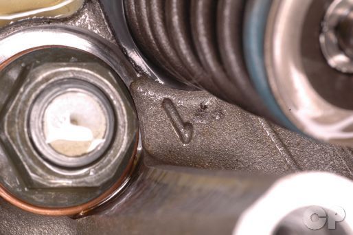
The cylinder is held on by 12 nuts, four cap nuts and eight open nuts. Loosen the nuts a little bit at a time with a 14 mm socket. The nuts are labeled by numbers cast in the cylinder head. Loosen the nuts in numerical order.


Remove the nuts and their washers. The outside four nuts have steal washers, but the rest have copper washers.
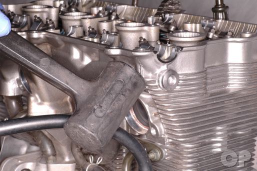
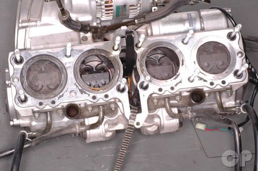
Lift the cylinder head off of the cylinders. Tap gently on the areas of the head without fins with a plastic mallet to free the dowel pins.


Free the oil pipes from the cylinder head as you lift the head off. Remove the O-rings on the oil pipes and replace them.
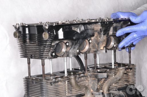
Hold the cylinder head by each side and lift it off of the studs.
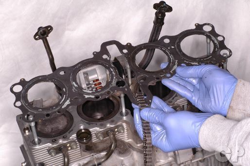
Remove the cylinder head gasket.


Remove the O-rings from the base of the studs. Lift out the dowel pins from each end of the cylinder block.
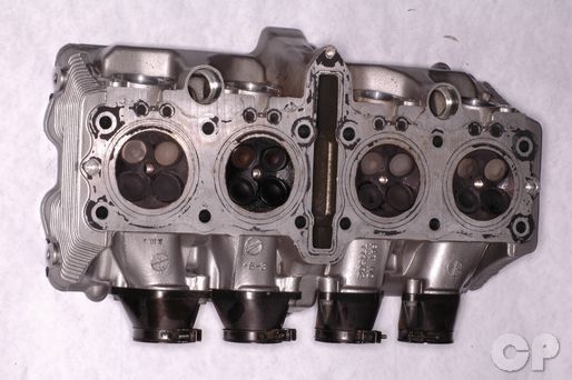
Clean the combustion chambers with contact cleaner, a plastic knife, brush and/or rag. Take care to only remove carbon and not scrape the head.
Place a straight edge across the bottom of the cylinder head and check for warp with a feeler gauge. You will need to check clearance readings from several places on the bottom of the cylinder head surface for warp. If the clearances are outside of specifications the head will need to be resurfaced or replaced.
(Service for Cylinder Head Warp is 0.2 mm or 0.008 in)
Disassembly
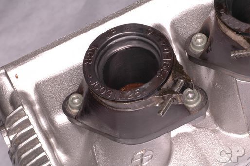


Note the position and orientation of the insulator boots so that they can be returned to their original positions.
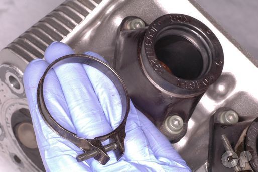
Remove the insulator clamp.


Remove the insulator bolts with a 5 mm Allen.


Remove the insulator and O-ring from the cylinder head. Discard the O-ring.


The four rocker arm shafts are each held in place with a set bolt. Loosen the rocker arm shaft set bolts with a 10 mm socket. Remove the set bolts and washers.


On the 1992 - 1997 Katana 600 models remove the rocker arm set bolts with a 5 mm Allen.


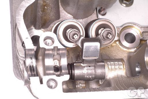
There is a caps on the end of each rocker arm shaft. Remove the rocker arm shaft caps with an 8 mm socket.


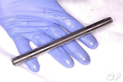
To remove the rocker arm shafts, thread an 8 mm (thread diameter) bolt into the shaft. Pull the bolt out and remove the rocker arm shaft. Note the location of the four rocker arm shafts so they can be returned to their original locations during reassembly. Inspect the rocker arm shafts for damage and wear.


Remove the rocker arms and springs. Inspect the rocker arms and springs for damage and wear. Note the location of the rocker arms so they can be returned to their original locations during reassembly.


On the 1992 - 1997 Katana 600 models there is one rocker arm per valve. Also, there is a spring that sits between the rocker arms and washers that sit on the outside of each arm.
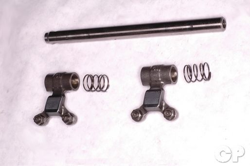
Measure the inside diameter of the rocker arms with vernier calipers and outside diameter of the rocker arm shafts with a micrometer. Replace the components as needed.
| Item | Specification mm (in) | |
| Rocker arm inside diameter | 12.000 - 12.018 (0.4724 - 0.4731) | |
| Rocker arm shaft outside diameter | 11.973 - 11.984 (0.4714 - 0.4718) | |
To remove the valves see the Valves topic.
Assembly
Install new O-rings into the insulator boots. Coat the O-rings in Suzuki "A" grease.
Special Tools- Suzuki Grease "A": 99000-25030
Install the insulator boots to their original position and orientation.
Apply blue Loctite to the threads of the insulator boot bolts. Tighten the boot bolts securely with a 5 mm Allen.
Install the boot clamps so that the screws sit on the bottom and the heads face towards the closest side of the frame.
Apply fresh engine oil to the rocker arms and rocker arm shafts.


Install the rocker arms, springs, and rocker arm shafts into the cylinder head.


Install the rocker arm shaft set bolt and washers. Tighten the set bolts to specification with a 10 mm socket or 5 mm Allen as required.
(Rocker Arm Shaft Set Bolt Torque: 9 N-m or 6.5 lb-ft)
Install the rocker arm shaft caps. Tighten the caps to specification with an 8 mm socket.
(Rocker Arm Shaft Cap Bolt Torque: 28 N-m or 20 lb-ft)
Installation


Install the dowel pins and new O-rings into the cylinder block.
Install a new head gasket on the cylinder block. Install new O-rings onto the oil pipes. Coat the O-rings in Suzuki "A" grease.


Install the cylinder head onto the studs.
Fit the oil pips into the cylinder head.
Install the cylinder head nuts and washers. The steel washers go with the outside nuts
Torque the cylinder head nuts to specification with a 14 mm socket. Tighten the nuts a little bit at a time and work your way around the nuts as numbered.
(Cylinder Head Nut Torque: 38 N-m or 27.5 lb-ft)
Install the cylinder head bolt and tighten it to specification with a 10 mm socket.
(Cylinder Head Bolt Torque: 10 N-m or 7.0 lb-ft)
Install the cam chain guide.
Install the camshaft. See the Camshaft Installation topic for more information.
Copyright 2025 - Cyclepedia Press LLC

Note: If you are viewing this document offline be sure to visit the latest version online at http://www.cyclepedia.com before attempting any repairs. Updates are made without notice.